
Layout and preview
Prepare a scene that matches the physical wiring.
Prerequisite: You need to know the fixture dimensions, starting corner and wiring direction.
Step-by-step instructions
Review the existing fixtures and scene boundaries in Patch. The starter drawing in a new project does not represent your own hardware.
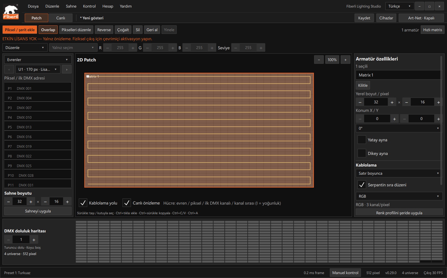
Patch workspace: fixture properties, pixel layout and DMX channel occupancy. Open the image to view it at full size. Select the fixture and adjust its dimensions, position and rotation to match its actual placement in the scene.
Match the starting corner, horizontal/vertical progression and serpentine settings to the wiring.
Use Ctrl + mouse wheel to zoom in. In Windows 0.33.1 and later, hold Space and drag with the left mouse button to pan. Resolve overlaps in the pixel order and DMX occupancy view.
Switch to Live and preview a chase effect with a clear direction. Save the project once the layout and wiring are correct.
In Windows 0.37.0 and later, open Building and use Load photo to select a PNG/JPEG. Prepare your patch fixtures first. Photos can be up to 16 MiB and 24 megapixels.
Choose Draw LED line and place points on the photo; one point is enough for a single product. Select the fixture, first pixel (starting at 1) and count, then save the line. Reverse direction only changes the photo mapping.
In Building, zoom with the wheel and pan with the middle mouse button; Fit resets the view. Drag the selected line’s orange points and save. Escape cancels a draft; Delete removes the selected line.
Set A/B mixing, master and blackout in Live, then check the Building preview. Photo and line edits do not start physical output; the shared Blackout control also affects running output. This view is not a photometric measurement.
Save the project and transfer the photo with it; the photo is not embedded. Use Load photo to relink a missing photo. Correct the fixture or pixel range if a red mapping error appears. Projects with building mappings use schema 27 and cannot be opened in earlier versions.
Expected result
Movement in the preview follows the planned physical pixel order.
Common mistakes and things to check
Scene coordinates and DMX order are different. Incorrect mirroring or serpentine settings can reverse the image even when the network is configured correctly.
These are screenshots of the actual application. Images are from Windows Studio 0.29.0; the Help screen is from 0.30.1. The screenshots show the Turkish interface. Physical output is disabled in the examples.